VW Tiguan Forum banner

Install Rear View Camera (RVC) to RNS-315 on 2011 Tiguan SEL

1 reading
72K views 47 replies 22 participants last post by  blazy20  
#1 ·
Hi,

This is my first post to any forum.

Learning from some of the posts online, i have purchased and installed the RVC.

But now i am stuck with the rvc wiring.

There are 2 sets of wires that can with the RVC.

One is the 26 pin cable that connects to the RNS-315. and the other one is the 3 wire cable for power and signal to the RCV. (Red, Blue and Brown)

i have connected the brown wire to the ground and the red wire to the fuse box for power. That was easy.
But i am confused about the blue signal wire.
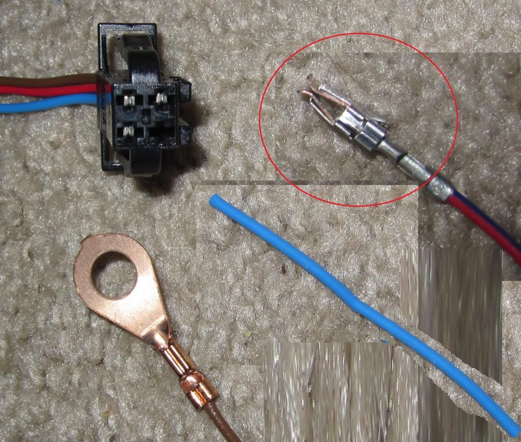
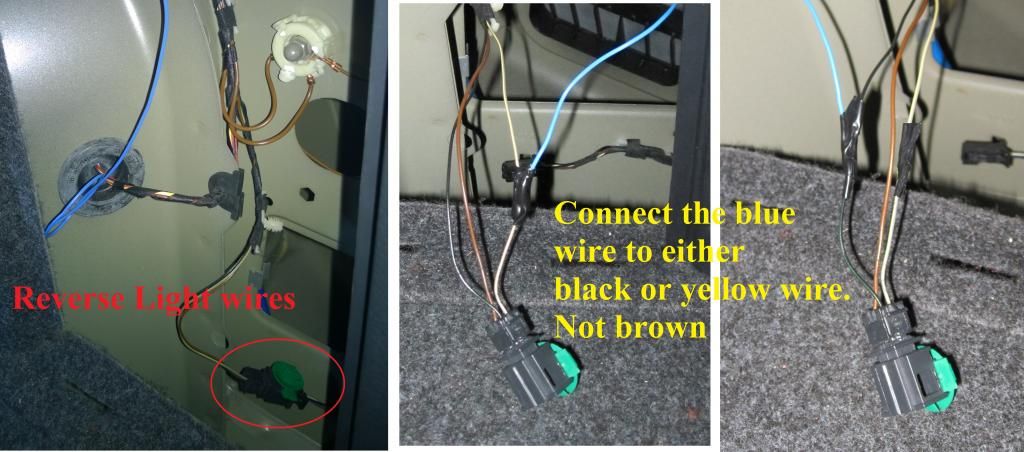
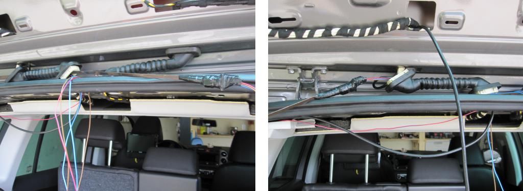
I have located the reverse light plug, which has 3 wires. Brown, Black and Yellow.(see attached photo).
The documents i have seen, and other online material say that the reverse light plug has is one brown and 2 blue/black wire, but mine is different. its brown, black and yellow. (see attached photo)
I check the brown wire, and that goes to the ground.
the black and yellow has no power untill when i put the car in reverse, both the wires, black and yellow, have 12v.
So i dont know i should connect the blue wire from the camera to the black or yellow wire.
I am going to add the photos of the whole installation once i have the RVC up and running.
Once i know where to connect the RVC blue wire and program the VCDS, i will upload the whole write up, which will help others too.

But first i need to solve the blue wire issue.
Please help me determine the correct wire.
Thanks
 

Attachments

Discussion starter · #2 ·
I have read in a forum that i can connect the blue wire to any of the the 2 wires (black/green or yellow/gray) that goes to the reverse light.

Apparently both the wires have 12v when i reverse, because they are meant for the 2 separate reverse lights, with a common brown ground wire.

Can someone please confirm that.
 
Discussion starter · #5 ·
Shawn,

Thanks for the reply.
I read that topic earlier, but that one has a controller unit, for moving lines, and it has 4 wires. So that did not help me.

But I did figure it out eventually. i tried on both the cable (Black/green and yellow/gray) where i have receiving 12V on reversing, and both are ok. so you can tap the blue signal wire to either on.

Kenderama,

i am soon going to post the whole installation procedures with pictures, that might help you installing the RVC.

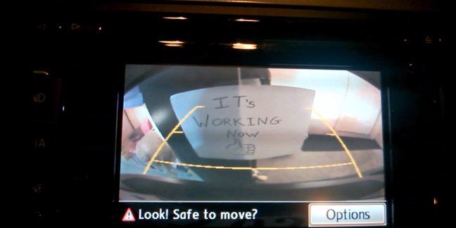
Meanwhile i have done the VCDS coding, and the camera works fine....... huuurrrrraaaayyy.....

here is the youtube link for that video...

 
THIS IS A GUIDE AND SHOULD BE USED AS SUCH. THE AUTHOR DOES NOT TAKE ANY RESPONSIBILITY FOR DAMAGE TO THE VEHICLE OR INJURY TO PERSON(S) FOLLOWING THIS GUIDE.

Finally…. I am done writing this up
I hope this is useful to some of us, who are planning to install a RVC in their VW.
(English is not my first language and you might find some mistakes and errors, so pardon me for that)

Installing a Rear View Camera (RVC) on a RNS-315 on VW Tiguan 2011 SEL
Tools and Equipment required
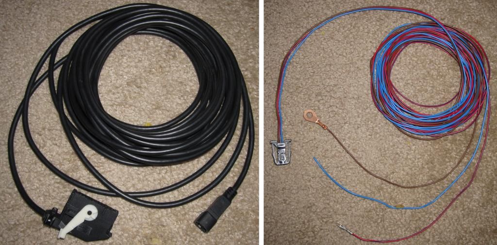
1. OEM VW Rear View Camera
2. RVC 26 pin video cable to RNS-315
3. Power & Signal cable to RVC
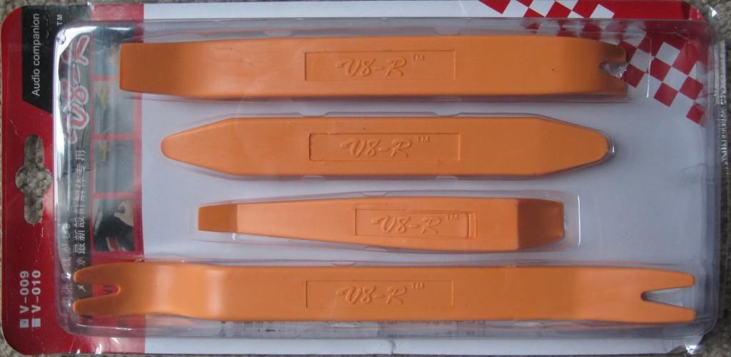
4. Car Trim remover tool
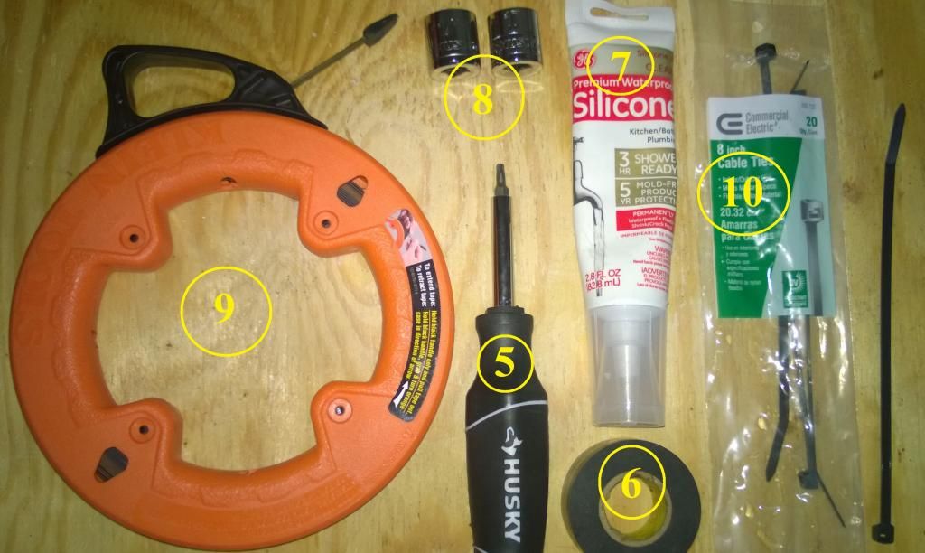
5. T-20 torx screw driver
6. Electric tape
7. Silicone (or some lubricating material)
8. 11/16" or 17mm socket
9. Fish tape
10. Tie wraps
11. 10mm socket
12. Vag com Hex can cable and VCDS software installed on a Laptop.

Where to buy these;
1, 2&3. I bought the camera from ebay for $180, which came with the 26pin video cable and the power-signal cable with proper connectors on both the ends. (Link : http://www.ebay.com/itm/360634324265)
4. I bought the car panel remover from ebay for $20.
5, 6, 7, 8, 9, 10, 11 at the local hardware store.
11. The original from vag com cable from Ross-Tech will cost around $300. (Or you can find someone from your city in this forum or any other VW forum, and ask them if they would help you program it with their cable and software)
(You can also find someone on this forum http://forums.vwvortex.com/showthread.php?4991419-Vag-Com-Locator-searchable-map-style!-Owners-pm-me-your-info-requested-in-the-thread)

1. OEM VW Rear View Camera
01_zpsca551bd2.jpg

2. RVC 26 pin video cable to RNS-315
02_zps17273ec8.jpg

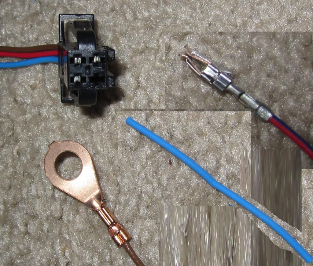
3. Power & Signal cable
03_zpsf8fbba35.jpg

4. Car panel Trim remover
04_zps3e72e11d.jpg

5. T-20 torx screw driver, 6. Electric tape, 7. Silicone (or some lubricating material),
8. 11/16" or 17mm socket, 9. Fish tape or long tie wrap, 10. Tie wraps
05_zpsb550916f.jpg

Step 1. Removing the RNS-315.

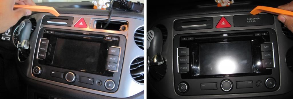
a. Using the trim removal tool remove the card storage slot and the passenger airbag indicator. You can disconnect the connector going to the passenger airbag indicator light or you can leave it connected.
06_zps812fde19.jpg

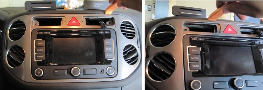
b. Using the T-20 torx screwdriver remove the 2 screws, one each, behind the card storage slot and passenger airbag indicator.
06a_zps6cb15cba.jpg

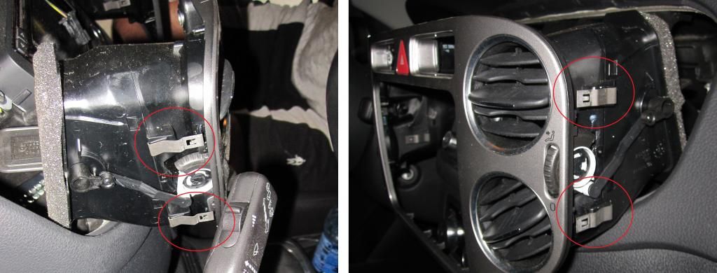
c. Again using the car trim removal tool, pry on the top side of the AC vent and RNS-315 trim. Don't pull it out completely as, there is a wire connected to the hazard light button. The trim is clipped with 4 clips, 2 clips on either side of the AC vents. See the second picture below
07_zpsea66fc0b.jpg

08_zps53ba4adf.jpg

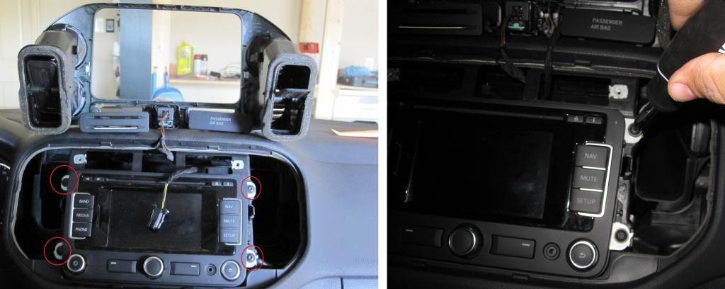
d. Remove the trim and place it over the dash board, upside down. Using the T-20 torx screwdriver remove the 4 torx screw, 2 screws on either side of the RNS-315. Please be careful with the screws, as they might drop inside and you may never recover it. I lost one.
09_zpsf1526feb.jpg
 
Step 2. Feed the 26-pin video cable to the RNS-315.

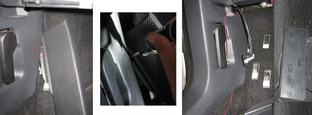
a. First you need to take the 26-pin end of the video cable and red power cable and pass it through the trim between the dead foot pedal and the hood opening lever. You can either remove the dead foot pedal, or you can use the fish tape and fish the 2 wires from bottom to top. The foot pedal has 3 sliding locks on the back and one torx screw behind the trim joint. i was able to remove the torx screw, but did not manage to put the screw back. So try the fish tape method, if you don't want to remove the screw.
10_zpsa718f39f.jpg

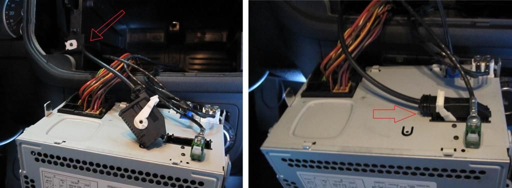
b. Now pull the RNS-315 to remove from its position and pass the fish tape through the opening in the backside. Push the fish tape through all the wires and steering column, and make sure it does not get caught up into anything. Tape the 26-pin video cable to the fish tape and pull it through the RNS-315 opening. Connect the plug to the 26 pin slot provided on the back of the RNS-315. Press the white tab on the connector to seat the plug properly into position.
11_zps5cdef755.jpg

c. Carefully put the RNS-315 back into its position into the Dash. Put the 4 torx screws on the RNS-315 using the T-20 torx screwdriver. Flip the RNS-315 panel trim back on top of the stereo and gently push it into position. Put the 2 torx screws, one on the card holder slot and one on the passenger airbag indicator slot. Connect the connector going to the passenger airbag light (if you removed it) and push it gently into its place. Then push the card holder gently into its place, and you are done putting the RNS-315 back into position.
 
Step 3. Adding the Red power wire to the Fuse box.

a. First you need to find a place in the fuse box where you want to Red power wire for the RVC.
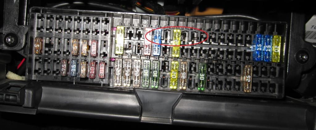
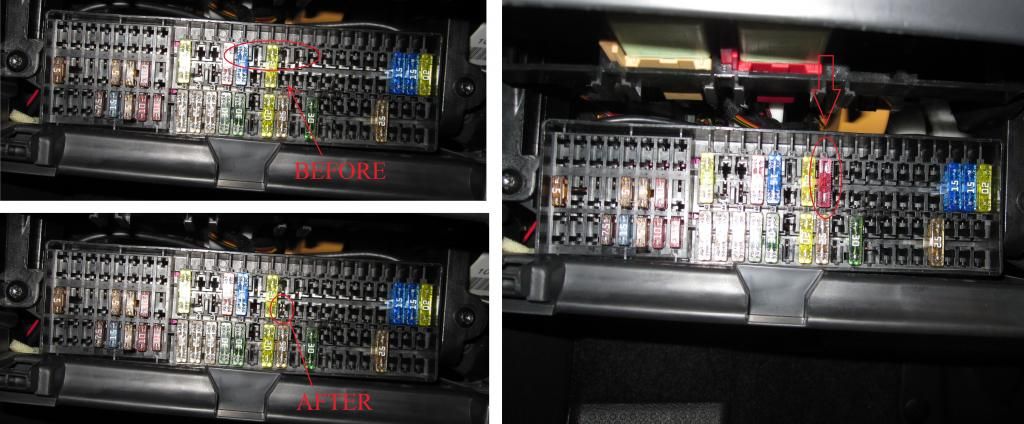
Access the fuse box, and look for the pin in the fuse box, where you can get 12V when the ignition key is turned to ON position and no power when the key it turned to OFF position. I found these 3 pins on the top side which measured 12V when I turned the ignition key ON.
12_zps32d27d0d.jpg

b. There are 2 ways you can add the red power wire to the fuse box.
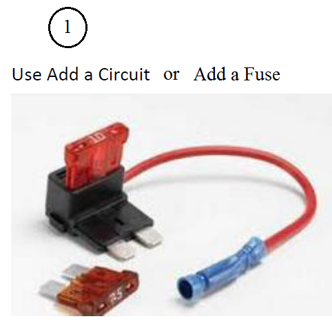
First, you can use something called Add a fuse or Add a circuit, which can be bought from ebay for $5. Just crimp the red power wire to the wire coming out of the Add a Circuit, and connect it into the Fuse box.
13a_zpsc6ae6db5.png

The second ways is the way I wired it, a bit professional, as the wire that came with the RVC, had the red power wire with the original fuse box terminal crimped at the end, which fits directly into the fuse box, from the back side. In order to do that you have to remove the 2 torx screws from the front of the fuse box plate. Then rock the fuse box sideways and angle it backwards on one side and push it back to get it out. Do not pull it out to the front side, as you can only work with it if you remove it from the back.
14_zps3c82a8ed.jpg

15_zps8c4761f4.jpg

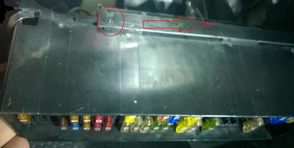
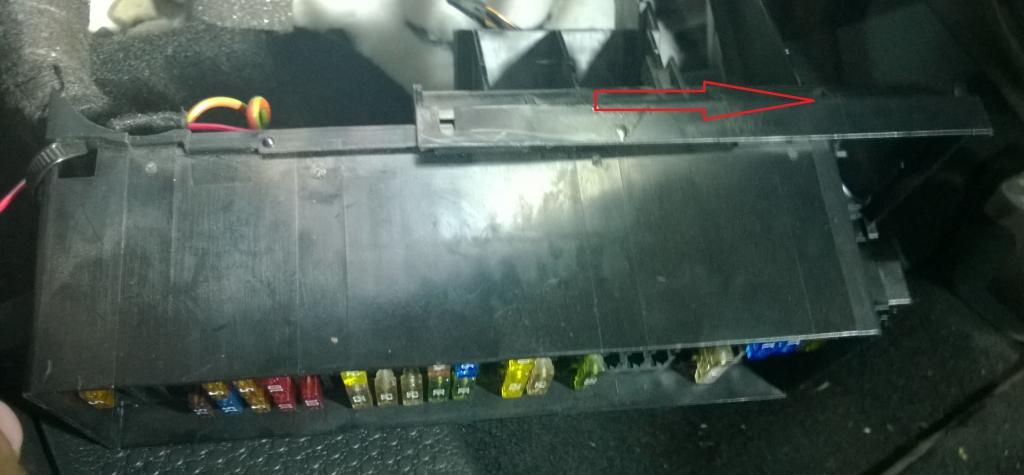
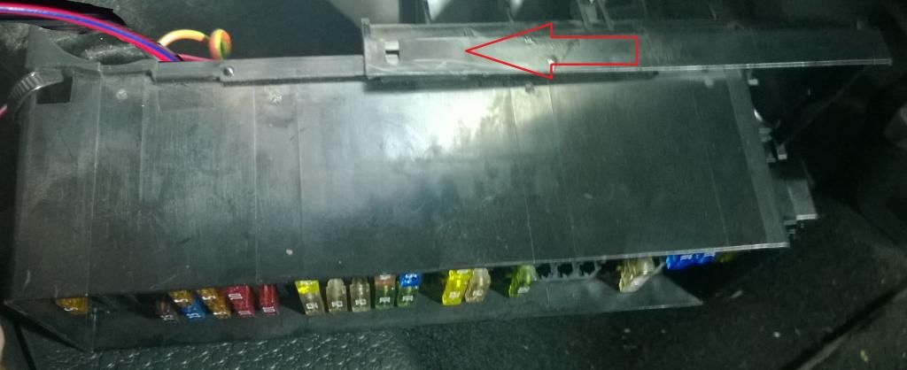
Push back the fuse box and down, to access the back side of the fuse box. There is a cover on the back side of the fuse box, which is locked by 2 round tabs, one on either side. Lift the end of the back cover, near the locking tab, just enough to release it from the tab, and slide it towards the right to get it off completely.
16_zps6a883db3.jpg

17_zpsc5885dab.jpg

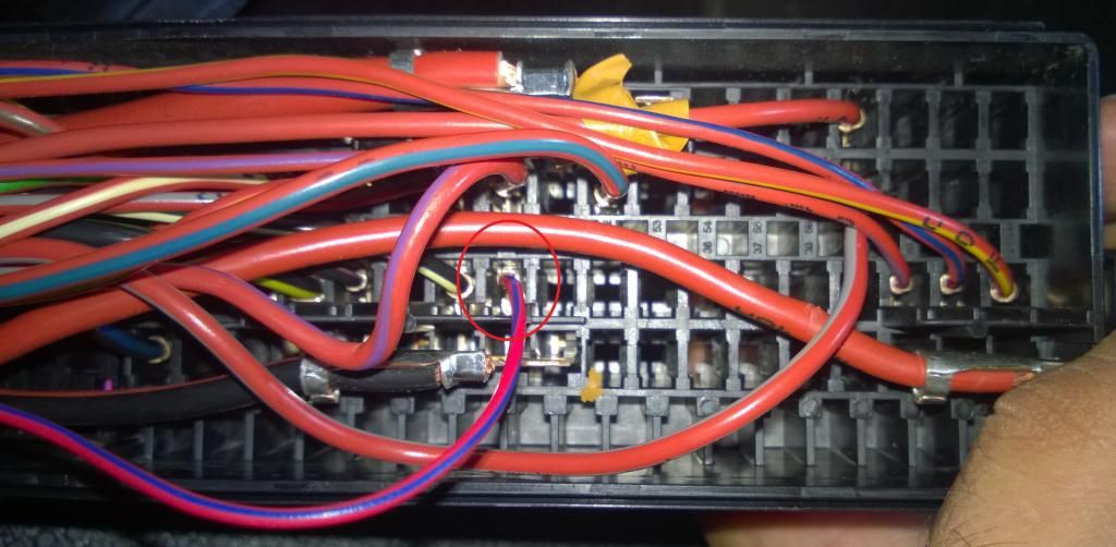
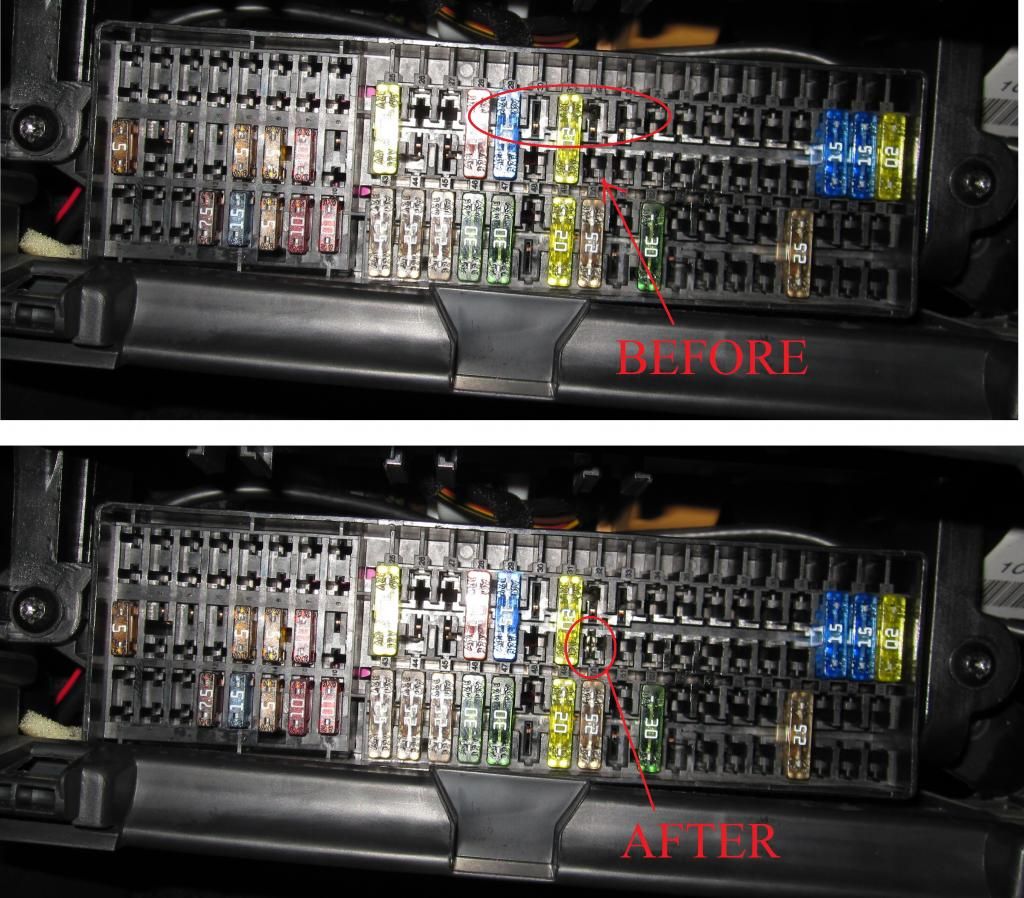
c. Now you will have access to the back side the fuse box. Locate the empty slot in the fuse box, where the top pin measures 12V when the ignition key is turned ON. Simply align the end of the red power wire, with the crimp terminal attached to it, and push it into the empty slot, until you hear a click. Try to give a gentle pull and see if the wire comes out. If it is does not come out, it means the terminal is set properly into the fuse box. Slide the back cover into place, until it is locks into the locking tabs on both sides. Be careful not to pinch any wire while doing that. Install the fuse box back into place; by angling it one side into the tab where the screw goes in and push it just enough to slide the other end of the fuse box into the other tab. install the 2 torx screws on the fuse box. You can see the before and after picture which shows the crimp terminal of the red power wire installed into the fuse box. Don't install the fuse right now, as we can do that once the complete wiring is done. Install the fuse after step 8 is done.
18_zpsca49b0e9.jpg

19_zps0caffaf9.jpg

20_zps6441c110.jpg
 
Step 4: Lay power wire and video cable to the trunk

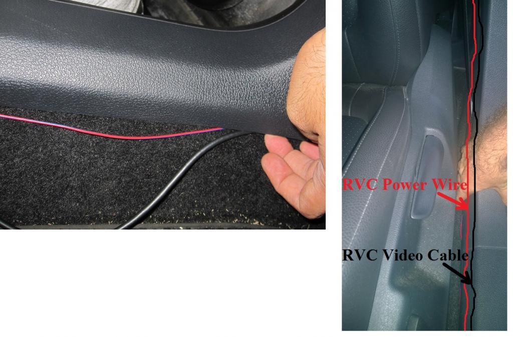
a. Take the red power wire and the video cable and just tuck it under the door bottom trim. Do the same for the front door trim and back door trim.
21_zps09c31996.jpg

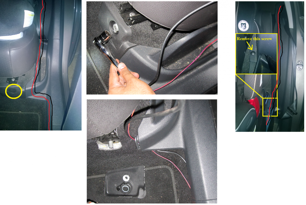
b. In order to pass the 2 cables through the trims below the back seat magazine holder, you need to remove a piece of the trim holding the magazine holder. To do that remove the small round plastic cover below the back seat, and open the nut inside it. You can use a 17mm or 11/16" socket to remove that nut. Remove the piece of trim holding the magazine holder and lift the magazine holder trim to tuck the 2 wires under it. Pass the 2 wires through it and up to the vents in the luggage compartment.
22_zpsc39fca72.png

c. Remove the 2 torx screw holding the vents in the luggage compartment, using the T-20 torx screwdriver.
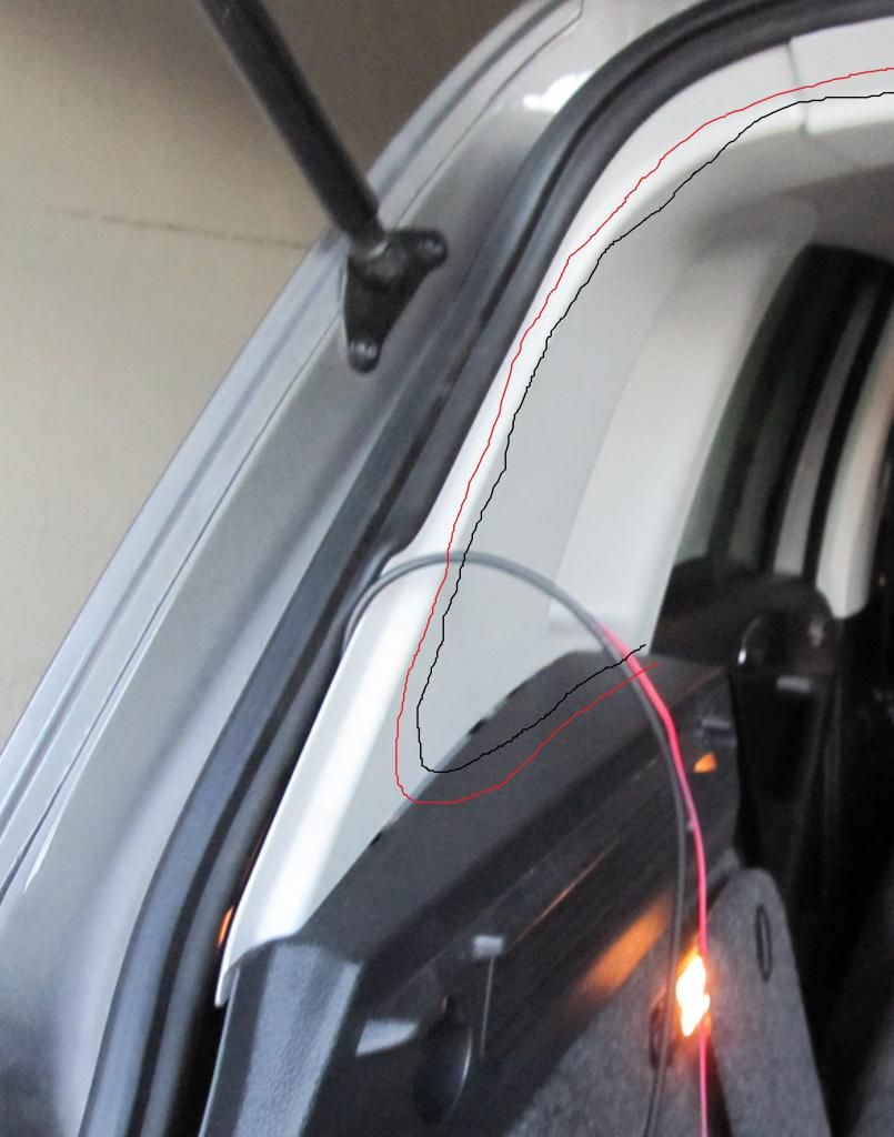
Pull out the vent and pass the red power wire and the video cable behind it. Then pass it through the corner of the white trim. Just pull the white trim enough to pass the 2 wires.
23_zpsee8007b7.jpg

24_zps110de795.jpg

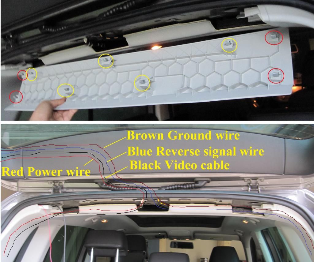
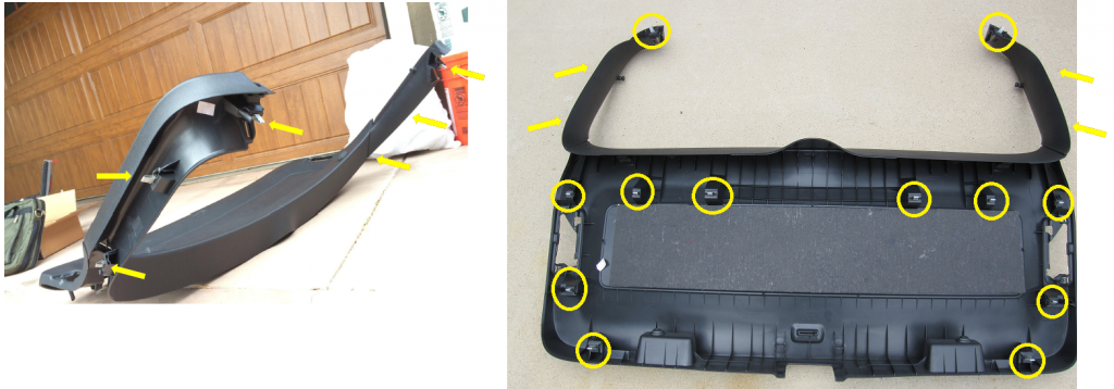
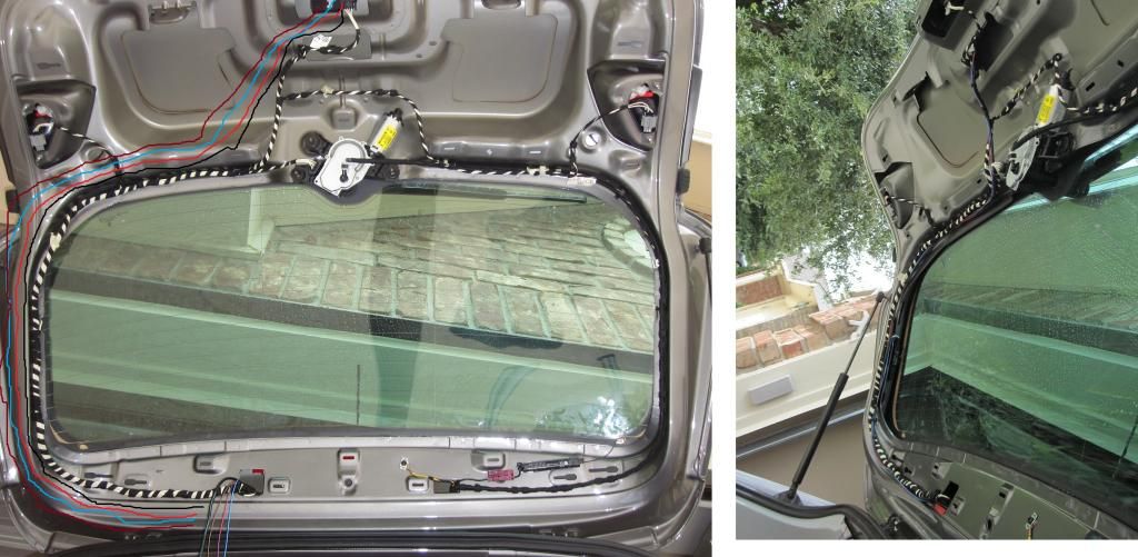
d. Now remove the center trim on the top of the luggage compartment. It is fixed with 9 metal clips. First remove the 4 clips from the ends, 2 on each end (marked on the picture with red circles). Then, using a bit of jerking force, pull the rest of the 5 clips. Once that trim is out, pass the red power wire and black video cable through the driver trunk trim, to the top of the luggage compartment.
25_zps489bcfe0.jpg

Step 5. Pass all the wires through the flexible rubber hose on the trunk door.

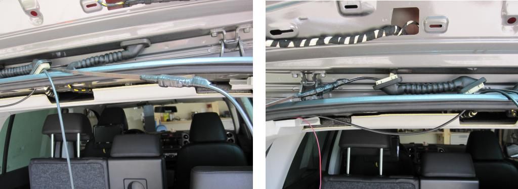
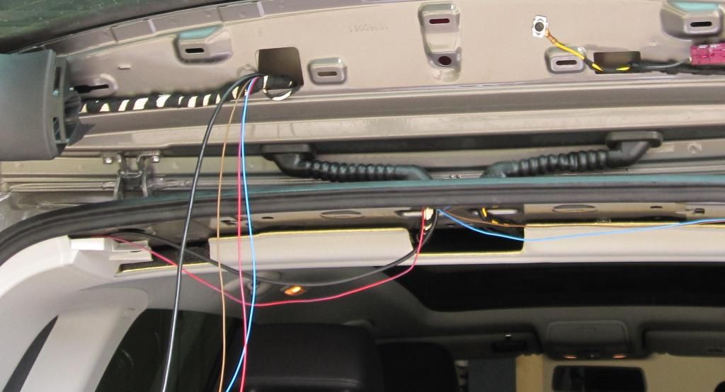
a. First remove the flexible rubber hose from the tabs. For the top tab, you can use one of the trim removal tool to release the 2 tabs holding the rubber hose on top. For the bottom tab, you can just use your finger or the trim removal tool to push it out. Once the flexible rubber hose is out, pass both the wires, the black video cable connector and the 3 wire camera connector though the bottom tab hole.
26_zps6fe17644.jpg

b. Next use the fish tape or something similar and push it from the top section to the bottom section of the rubber hose. Tape the video cable connector to the fish tape. Apply ample quantity of some kind of lubricant, like silicone to the taped section. This is very important, or else you won't be able to pass the 2 cables through the rubber hose. Pull it slowly until it comes out of the top end.
27_zps0e1c0156.jpg

28_zps868738ed.jpg

c. Next pass the 3 wire camera cable connector through the rubber hose. Repeat the same previous steps. Use the fish tape or something similar and push it from the top section to the bottom section of the rubber hose. Tape the 3 wire camera cable connector to the fish tape. Apply ample quantity of some kind of lubricant, like silicone to the taped section. This is very important, or else you won't be able to pass the 2 cables through the rubber hose. Pull it slowly until it comes out of the top end.
29_zps65aaf4d3.jpg

d. Once both the cables are out of the top end of the rubber hose, pass then through the top tab hole and remove them from the hole above it, where another white bundle of cable is coming out. Push the top and bottom tabs of the rubber hose into place.
30_zps3cb5b09f.jpg
 
Step 6. Lay out and connect the brown ground wire and the blue reverse signal wire.

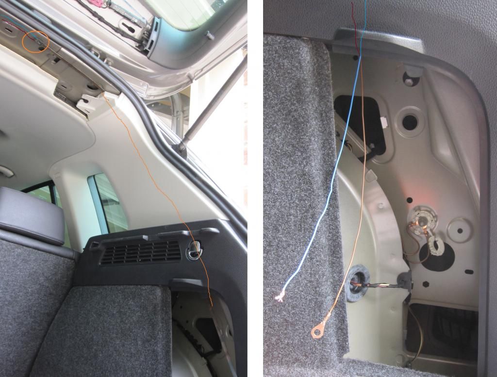
a. Just to remind you again, the red power wire, that we laid from the fuse box to the trunk, has a 4 pin connector at the other end, with one brown ground wire, one blue reverse signal wire, one red power wire and a blank. Now you need to lay the brown and blue wire from the top of the trunk trim that we removed, to the storage box on the passenger side of the trunk. Open the passenger side storage compartment, and push a fish tape from bottom to the top of the trunk, through the white trim. Tape the blue and the brown wire to the fish tape and pull it out of the storage compartment.

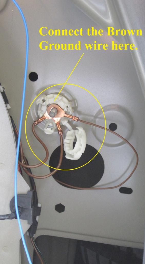
b. Connect the ground wire to grounding point available in the passenger side storage compartment. Remove the cover off the white connector and use a 10mm socket or wrench to loosen the nut. Guide the brown wire onto the bolt, through one of the slots available on the white connector. Tighten the nut back and you should have good ground now.
31_zps40bc52a5.jpg

32_zps0611c2cb.jpg

c. Now connect the blue wire to the reverse light power wire. The connector for both the reverse lights, is located in the passenger side storage compartment, just below where you grounded the brown wire. The plug has 3 wires, one brown ground wire and two power wires for the two reverse lights, black/green and yellow/gray. The power wire color can be different in different vehicles. You can use any of these powers to connect the blue wire. I tried both and the camera works with both of them.
33_zpsbfd6421a.jpg

Step 7: Remove the black trim from the trunk.

(Here is a YouTube video that I have uploaded
)

a. Remove the 2 torx screws from the bottom part of the trunk trim. The screws are covered with a plastic tab over it.
34_zpsfc506e89.jpg

35_zps9e53881a.jpg

b. Now pull the trim off the trunk, which is fastened to the trunk with metal clips. There are total 16 clip on the trunk trim. 2 at the top end, one on each side. To remove them pull them directly toward you. 4 on the side of the truck glass, 2 on each side. To remove them, pull them towards the center of the trunk glass. And 10 on the bottom trim panel. Some of the metal clips are really tough to remove and you will have to use some force to get them off. Try to jerk the trim with some force to unseat the metal clips.
36_zps3e1c2117.png

Step 8: Lay the 2 cables and connect it to the RVC.

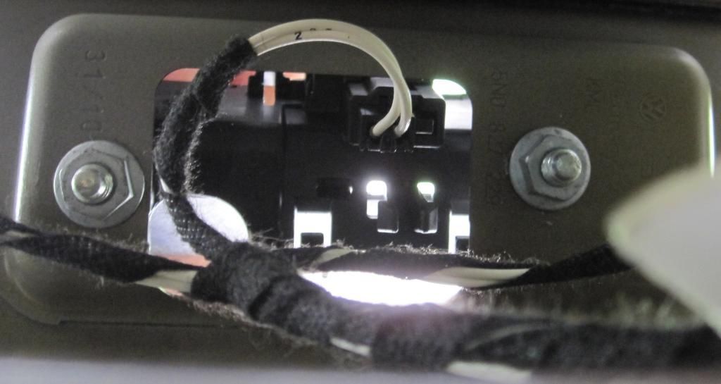
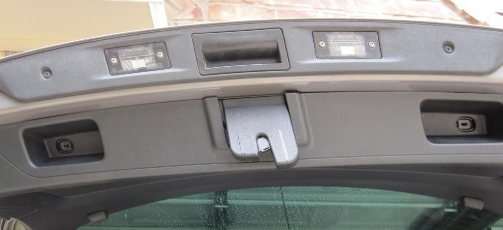
a. First remove the trunk switch from its place. Use the 10mm socket wrench with a socket extension and remove the 2 nuts over the trunk switch. Unplug the connector from the switch.
37_zps18c7db7b.jpg

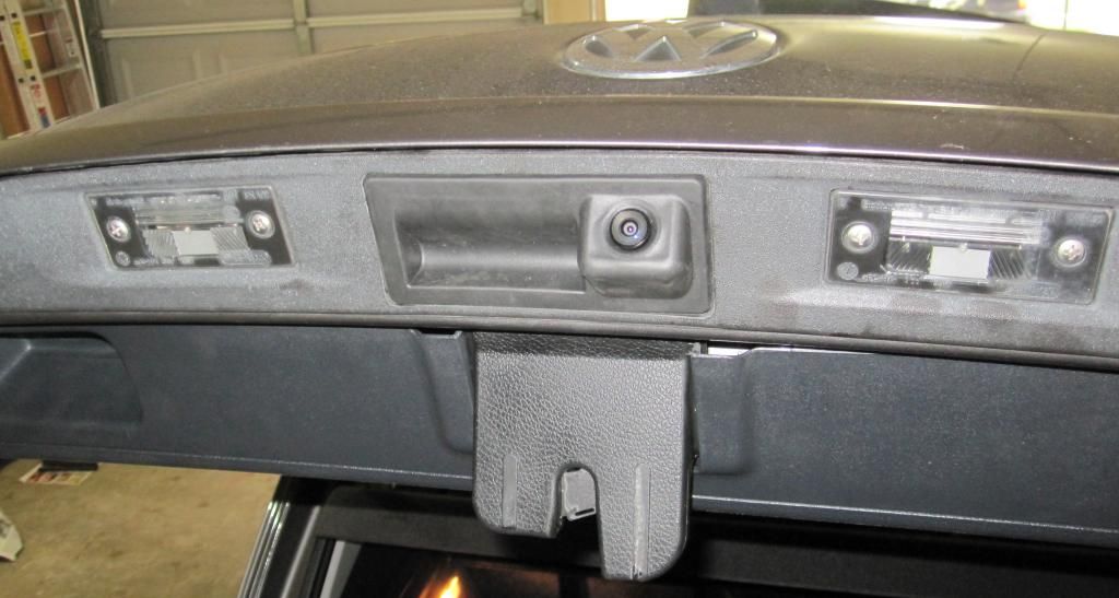
b. Now lay down the 2 cable, the black video cable and the 3 wire RVC cable, along with the white wire bundle. Pull the connectors of both the cables out from where you removed the trunk switch. Now get the RVC and connect both the connectors to the 2 plugs on the RVC. Both connectors should click easily onto the RVC. Place the RVC in place of the switch, and then fasten it using the same two 10mm nuts that you previously removed.
38_zpsf49fee0d.jpg

c. Now use some tie wraps or you can use electric tape, to tie the 2 cable to the white bundled wire. If there is any extra wire tie it at with the bundle. Once the 2 cables are tied in properly, put back the truck trim. Also put back all the other trims that were removed. (Here is the video on how to reinstall the trim back to its place
) Clean up all the tools and other stuff from the car, to get ready to enjoy the camera.
39_zps357c212e.jpg
 
Step 9: VCDS vag com programming and testing the camera.

a. First thing, put a 10A fuse into the fuse box where you installed the red power wire for the RVC, in step 3c.
40_zps0ca40418.jpg

b. Now you are ready to program the car to enable the RVC. Bring the vag com HEX CAN cable and laptop with the VCDS software installed. Connect the USB end of the vag come cable to the laptop. If this is the first time you have connected the vag com cable, wait till the driver is properly installed on the laptop. Now connect the 16 pin end of the vag com cable to the connector below the fuse box. The light on the vag com cable, 16 pin end, will glow red and then turn green. Once the light turns green, turn the car key ON. No need to start the car.

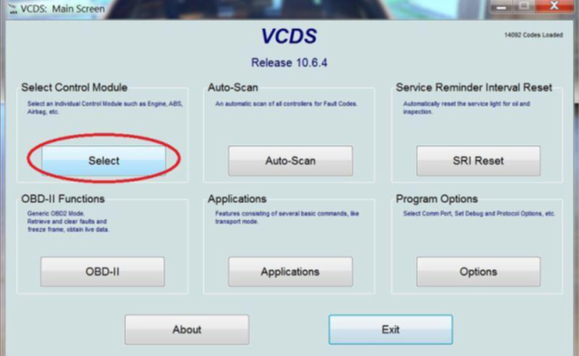
c. Open the VCDS software on the laptop. Once the software is running, click on SELECT CONTROL MODULE
(Here is a small video that I have uploaded on YouTube on how to program the system using the VCDS software.
)
42_zps169095fc.png

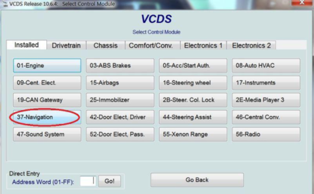
d. Click on 37-NAVIGATION
43_zps83b7d57e.png

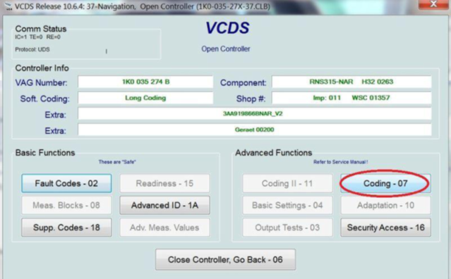
e. Click on CODING-07
44_zps428eed99.png

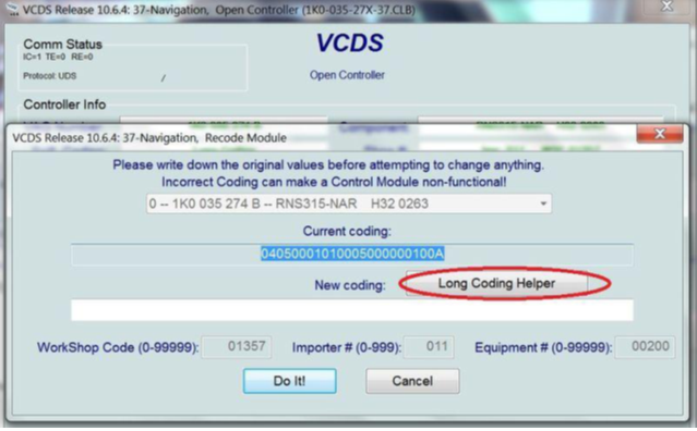
f. Click on LONG CODING HELPER
45_zpsf22471df.png

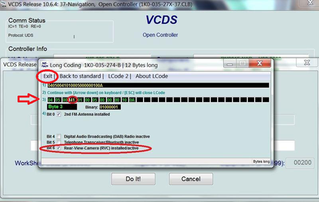
g. Click on the 4th window on row 3)
(the color of that window will change from green to yellow)
CHECK the Bit 6 - Rear-View-Camera(RVC) installed/active.
Then click EXIT, on the top left corner of the window.
46_zps8db85fc7.png

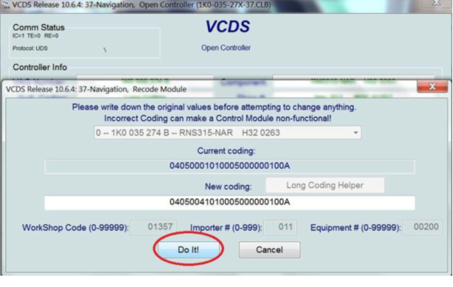
h. Click on DO IT!
47_zps3c897f8e.png

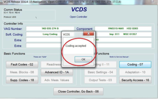
i. Once you see the message "CODING ACCEPTED", click OK.
48_zps657a3822.png

j. Programming is done. Close all the other windows and remove the vag com cable from the car.
Start the car.
Put the gear shifter into REVERSE…
……. and ………. BINGO…..
49_zps8a2ef24a.png

(Here is a small video that I have uploaded on YouTube on how to program the system using the VCDS software.
)

Hope I have explained it well enough for everyone to understand and DIY.
Let me know if you have any questions
 
Discussion starter · #16 ·
Thanks Enigma..
And Thanks Old Dog... For adding that disclaimer as well.
As i said before, hope this is useful to someone (like Kenderama ) who is planning to install one.

I read a lot of posts before starting this and i realized that none of them 100% material, and most of it was to be assumed. Thats the reason i added more pictures to help people understand the process better.

Cheers...
 
Discussion starter · #18 ·
Also if anyone needs the vag com cable and the VCDS programming software for the RVC, i stay in Dallas Fort Worth area and would be happy to assist anyone who need it.
Disclaimer: Use at your own risk, as it is not a genuine cable. It worked for me.
 
Discussion starter · #22 ·
From what i know the only difference, is that with the controller, the yellow line on the sceen are moving with the car, when you reverse.

To set it up you have to do some calibration, and from what i have read, a lot of people have issues with calibration and moving line. But i could be wrong.

Here is a video i found showing moving lines


Here is another one without moving lines.

 
Discussion starter · #32 ·
Anyone who needs the full DIY with photos, please pm me with your email address and i will send you the DIY with photos.
Recently Photo Bucket stopped free hosting of photos on third party website, and virtually asking for ransom, which i am not paying to them.
Fell free to pm me, and done forget to send me your email address.